Electrical Relays in the Porsche 356
by Jim Hinde
The topic for this session is relays: how they work, how the
factory used them in the 356, and popular additional applications for
them on the cars today. The car on the lift at today's session has
a starter relay kit installed, and we will take a detailed look at it.
What is a relay, and how does it work?
A relay is an electrical switch that is operated by an electromagnet.
When the electromagnet's coil receives current, the magnet pulls a
spring-loaded hinged plate away from its normal position, causing one or
more pairs of electrical contacts to open or close. These contacts
are called NC (normally closed) or NO (normally open) according to their
position when there is no current moving through the coil. A relay
can have only NC contacts, only NO contacts, or both types. The
photo below shows the inside of a 356B's light signal relay (LSR), which
has both NC and NO contacts. When its coil is energized, the
hinged plate is pulled downward by the electromagnet, opening the NC
contacts and closing the NO contacts. The numbers shown on the
terminals on the base of the relay are the same ones that are stamped
next to them on the base board.
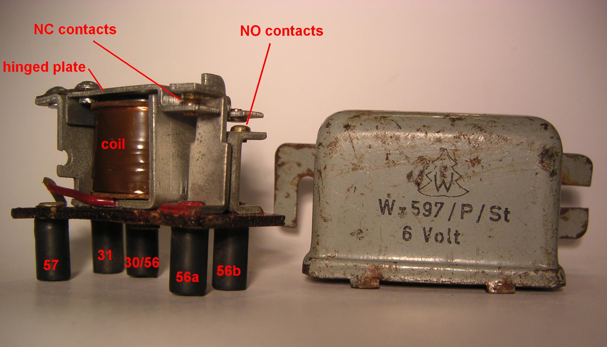
The terminals on the relay are wired internally as follows: 57 and
31 to the two ends of the coil, 30/56 to the hinged plate (which holds
the lower contact of the NC pair and the upper contact of the NO pair),
56a to the upper NC contact, and 56b to the lower NO contact.
How did the factory use relays in the 356?
One use for relays in the 356 is to allow the state of one circuit to
control another circuit. An example of this is the LSR shown
above, which controls whether it is the high or low beams that are
activated when the turn signal lever is pulled toward the driver in a T5
or T6 car, based on the position of the light switch.
In this case the first circuit includes the relay coil and the light
switch. When the light switch is in the park position (pulled out
one stop, parking lights on but headlights off), power is supplied to
the relay coil by a wire running from terminal 57 on the light switch to
terminal 57 on the relay. When the light switch is in any other
position, this wire is dead and no current reaches the coil. Terminal 31
on the relay is connected to ground.
The second circuit includes the signal/dimmer switch, the relay contacts
and the headlights. Strictly speaking, it is one of two different
circuits, depending on the position of the contacts. When the
lever is pulled to flash the lights, power is supplied to relay terminal
30/56 by a wire running from terminal 56a on the signal/dimmer switch.
If the relay is in the normal state—that is, if the lights are off
altogether or the headlights are on—the NC contacts remain closed and
the current flows through the NC contacts to the high beam lights via a
wire running from relay terminal 56a to the fuses for the high beams.
If the relay is activated—if the parking lights alone are on—the NC
contacts are opened, the NO contacts are closed, and the current flows
through the NO contacts to the low beam lights via a wire running from
relay terminal 56b to the fuses for the low beams. (The rationale for
making the lights behave this way is complicated and makes sense only
when you consider that the car may be equipped with fog lights:
the goal is to prevent flashing of the headlights from cutting out the
fog lights, which are prevented—by, yes, another relay—from being on at
the same time as the high beams.)
A second reason to use a relay is to reduce the amount of current
running through a switch that controls a high-current device. An
example of this on the 356 is the horn relay, where only the NO contacts
are used. The horn relay's coil is connected to the battery at one
end and to the horn button in the steering wheel on the other end.
When the horn button is pressed, the second end is connected to ground
and current flows through the relay coil. The relay's NO contacts
are connected to the battery on one side and the horns on the other.
When the relay coil gets power and the contacts close, battery current
flows to the horns. The important thing here is that the current
flowing through the horn button is only the very small amount needed to
power the electromagnet in the relay, while the current flowing through
the relay contacts and the horns is many times greater. This saves
wear and tear on the horn button, and it serves as a model for
latter-day add-on applications.
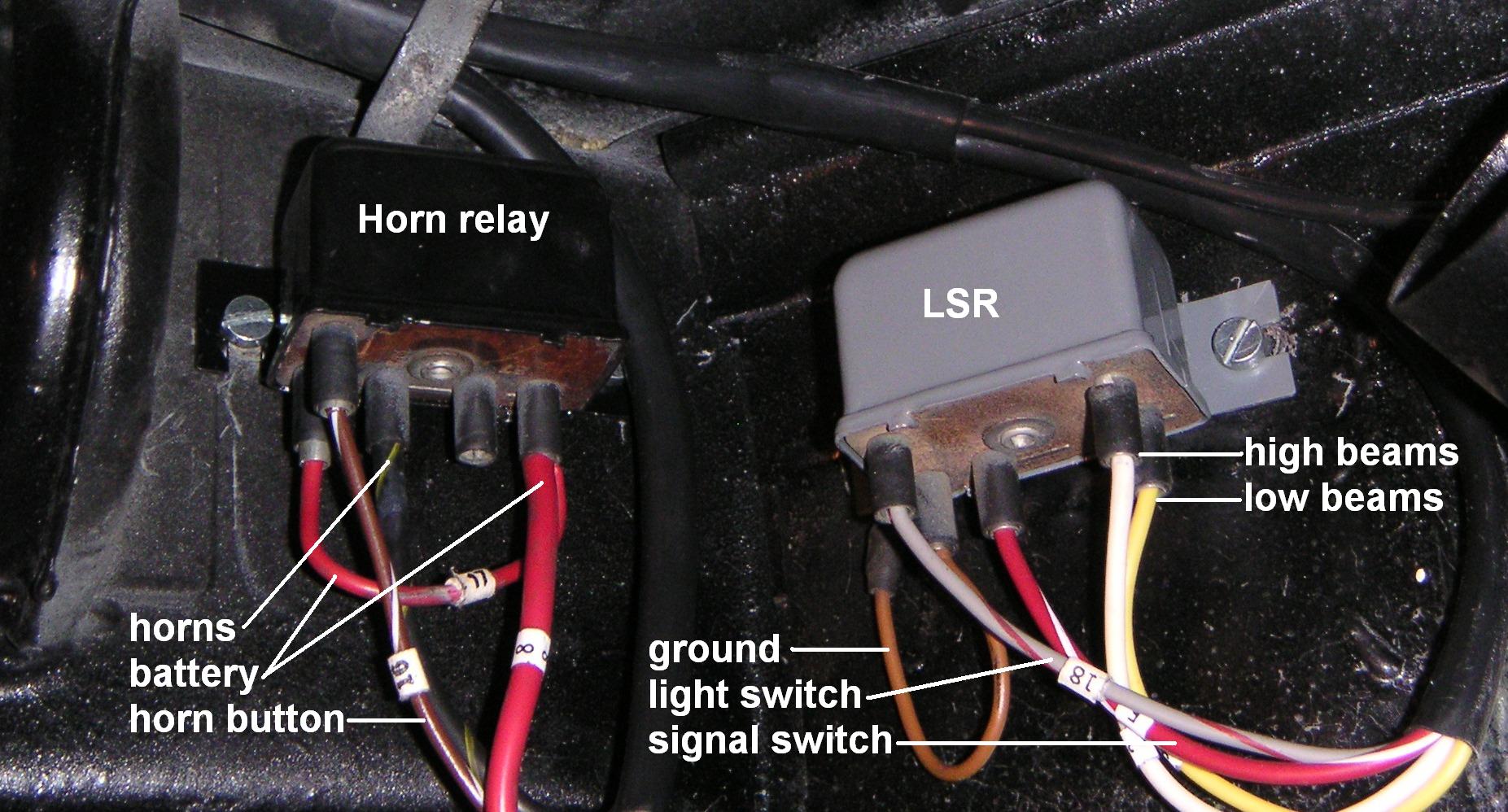
The photo below shows the horn relay and LSR in their factory location
for a T5 356B, which is on the right-hand end of the bulkhead behind the
dashboard. In T6 cars the relays are located in the trunk directly
above the fuse block.
Why do present-day 356 owners install additional relays in
their cars?
Because the control switches on the 356 are expensive to replace,
because their internal contacts will deteriorate more slowly over time
if the current load on them is reduced, and because worn contacts in a
switch create resistance that will reduce the amount of current that
reaches the devices controlled by that switch, a couple of strategically
placed relays can pay for themselves many times over in the long run and
improve the performance of the electrical system. The most popular
applications are the headlights and the starter solenoid.
Headlight relay. As we have seen, on 356B and later
models, current for the headlights goes through both the light switch
and the turn signal/dimmer switch. The latter go for over $200
when they are available at all. If the original headlights have
been replaced with halogen units, the current is even higher, more than
the switches were designed to handle in the first place and therefore
even more dangerous to their long term health. The 356 Electrics
headlight relay kit includes two relays, one for the low beams and one
for the high beams, that are installed directly upstream from the two
pairs of headlight fuses. This has the advantage of retaining the
original fuse protection.
Many owners install relays in order to cure the problem of dim
headlights. If the reason for the dim lights is resistance in the
switches due to wear, installing the relays will make the lights
brighter. But dim headlights can also be caused by other problems
that installation of relays will not solve, particularly by bad ground
connections to the bulbs. The ground for each headlight is a brown
wire that emerges from the wiring harness along the side wall of the
spare tire well and is attached to that wall with a screw and nut.
If that attachment does not make a good electrical connection, the
headlight on that side will be dimmer than it should be.
Starter relay. Two wires power the starter: a big,
fat one that runs directly from the battery and a small on that runs
from the ignition/starter switch. The small wire carries power to
the solenoid, and when the starter is engaged this wire carries up to 30
amps, all of which goes through the switch as well. With a relay
installed, the current through the switch is reduced to what is
necessary to power the relay coil, less than ½ amp. Installation
of the relay is simple, because the relay is mounted directly on the
starter and all the necessary electrical connections are right at hand:
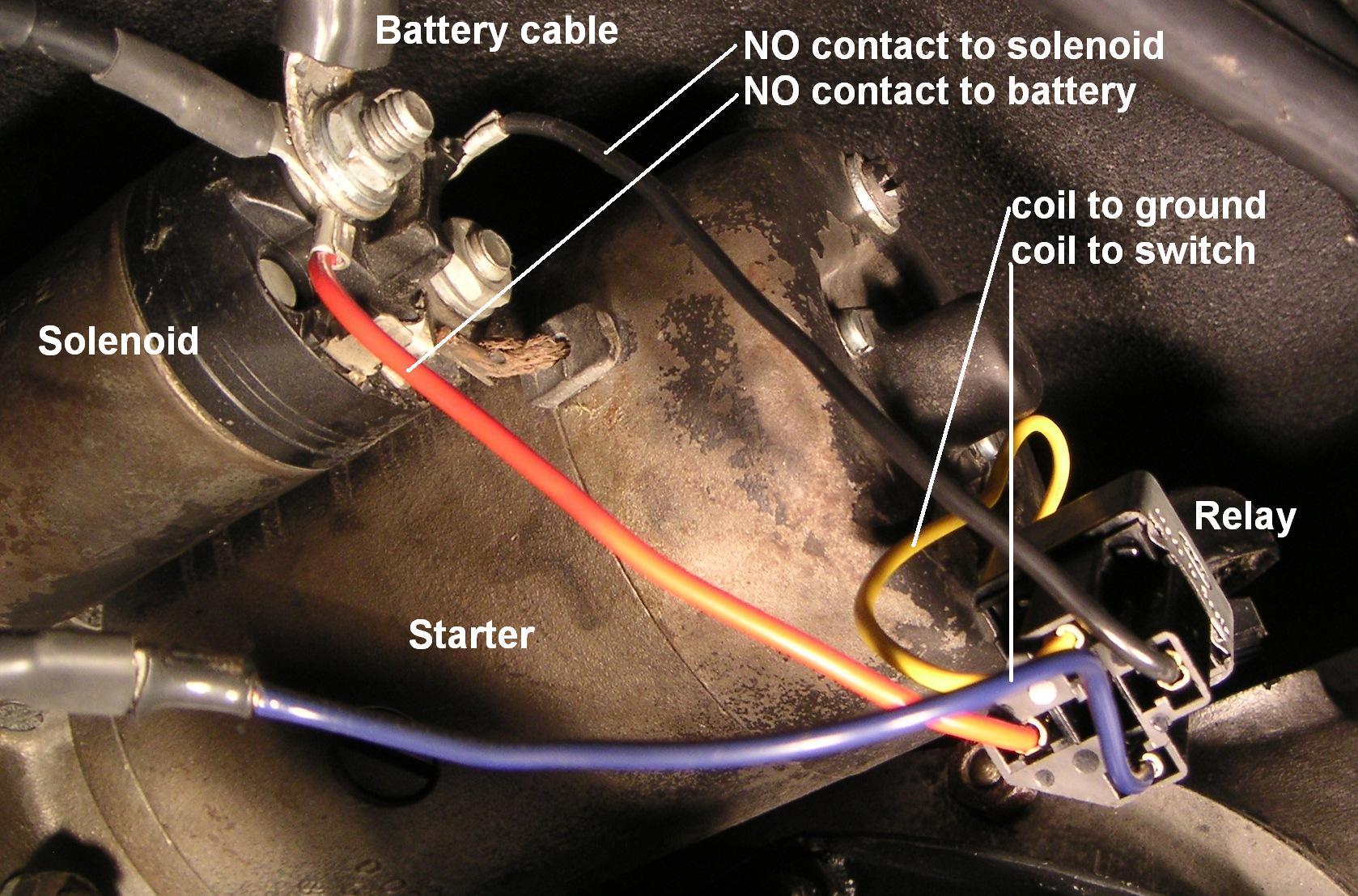
With the starter relay in place, when the starter switch is engaged
the relay coil receives current and the NO contacts close, connecting
the solenoid directly to the battery.